[Yocto-BBB] 8. Connecting an SSD1306 0.96 inch OLED over I2C
Translated from the Vietnamese original; wording may still be rough. Read the original →
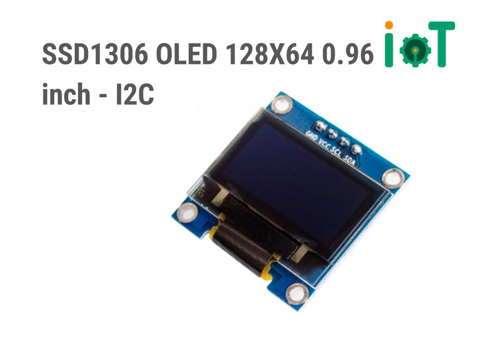
In this post I show you how to connect the Beaglebone Black to an SSD1306 screen and create recipes to build a program for it. Below is how to wire it
(If you run into difficulties following the blog, you can refer to my hands-on video at the end of the post)
1. Testing the connection
1.1 Adding packages to the image
Before creating recipes and code in yocto, I like to test on the real hardware first to be safe :v. For testing I add the following packages to the board: gcc, nano, i2c-tools (which has the very handy i2cdetect tool)
Gcc belongs to packagegroup-core-buildessential, so I install the whole group. This is the change in custom-image-minimal.bb
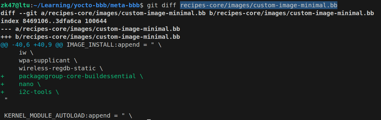
Flash again and we have an image with those tools
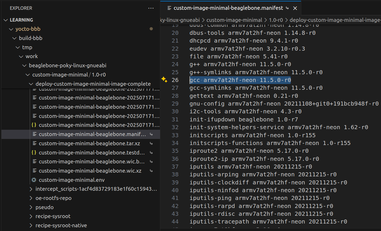
You can check the packages in the manifest file in the same deploy-image folder to see whether your packages really are in the image
1.2 Testing the i2c connection
1.2.1 Checking that i2c is enabled
This is the pinout of the Beaglebone Black
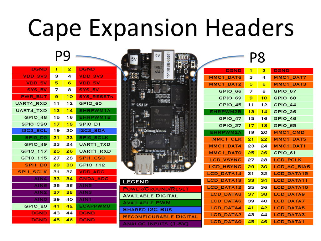
We see the board already exposes 2 pins of I2C2 at P9-19 and P9-20, so we check whether it is enabled with 2 commands
ls -l /dev/i2c*
root@beaglebone:~# ls -l /dev/i2c*
crw------- 1 root root 89, 0 Jan  1  2000 /dev/i2c-0
crw------- 1 root root 89, 2 Jan  1  2000 /dev/i2c-2
We see i2c-2 appears, but that is the software name, which may not match the real name in the Reference manual, so we have to check more carefully.
ls -l /sys/bus/i2c/devices
root@beaglebone:~# ls -l /sys/bus/i2c/devices/
total 0
lrwxrwxrwx 1 root root 0 Jan  1  2000 0-0024 -> ../../../devices/platform/ocp/44c00000.interconnect/44c00000.interconnect:segment@200000/44e0b000.target-module/44e0b000.i2c/i2c-0/0-0024
lrwxrwxrwx 1 root root 0 Jan  1  2000 0-0034 -> ../../../devices/platform/ocp/44c00000.interconnect/44c00000.interconnect:segment@200000/44e0b000.target-module/44e0b000.i2c/i2c-0/0-0034
lrwxrwxrwx 1 root root 0 Jan  1  2000 0-0050 -> ../../../devices/platform/ocp/44c00000.interconnect/44c00000.interconnect:segment@200000/44e0b000.target-module/44e0b000.i2c/i2c-0/0-0050
lrwxrwxrwx 1 root root 0 Jan  1  2000 0-0070 -> ../../../devices/platform/ocp/44c00000.interconnect/44c00000.interconnect:segment@200000/44e0b000.target-module/44e0b000.i2c/i2c-0/0-0070
lrwxrwxrwx 1 root root 0 Jan  1  2000 2-0054 -> ../../../devices/platform/ocp/48000000.interconnect/48000000.interconnect:segment@100000/4819c000.target-module/4819c000.i2c/i2c-2/2-0054
lrwxrwxrwx 1 root root 0 Jan  1  2000 2-0055 -> ../../../devices/platform/ocp/48000000.interconnect/48000000.interconnect:segment@100000/4819c000.target-module/4819c000.i2c/i2c-2/2-0055
lrwxrwxrwx 1 root root 0 Jan  1  2000 2-0056 -> ../../../devices/platform/ocp/48000000.interconnect/48000000.interconnect:segment@100000/4819c000.target-module/4819c000.i2c/i2c-2/2-0056
lrwxrwxrwx 1 root root 0 Jan  1  2000 2-0057 -> ../../../devices/platform/ocp/48000000.interconnect/48000000.interconnect:segment@100000/4819c000.target-module/4819c000.i2c/i2c-2/2-0057
lrwxrwxrwx 1 root root 0 Jan  1  2000 i2c-0 -> ../../../devices/platform/ocp/44c00000.interconnect/44c00000.interconnect:segment@200000/44e0b000.target-module/44e0b000.i2c/i2c-0
lrwxrwxrwx 1 root root 0 Jan  1  2000 i2c-2 -> ../../../devices/platform/ocp/48000000.interconnect/48000000.interconnect:segment@100000/4819c000.target-module/4819c000.i2c/i2c-2
Quite long, but we only care about the address; here we see 2 addresses: 4819c000 and 44e0b000
Checking the Reference Manual
, Section 2. Memory Map, and searching for those addresses 4819_c000 and 44e0_b000 (it takes a while to find them), we get the I2C2 address on page 183 and I2C0 on page 180


So i2c-2 here really points to i2c2 in the hardware and is enabled, so we can just use it :v
After these 2 commands we have confirmed that i2c-2 really is i2c2 in the hardware and is enabled, so we can use it
1.2.2 Checking with i2cdetect
We connect the Beaglebone Black to the SSD1306
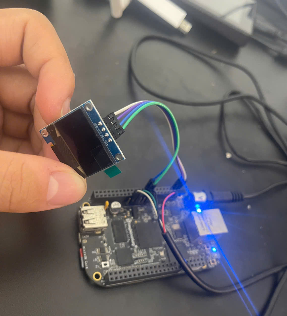
- SSD1306 GND <---> BBB GND (P9.1)
- SSD1306 VCC <---> BBB VDD (P9.3)
- SSD1306 SDA <---> BBB SDA (P9.20)
- SSD1306 SCL <---> BBB SCL (P9.19)
We run the command below to detect the address; note the param '2' is i2c-2; for i2c-1 it would be (i2cdetect -y -r 1)
i2cdetect -y -r 2
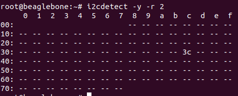
The board detected the screen's address. I2C is master/slave, so there is always an address to connect to
2. A program to print text on the SSD1306 screen
(You can refer to this video to practise with the ssd1306 package already available in Yocto, but here I want to test with a little C program of my own :vv ssd1306 https://www.youtube.com/watch?v=ReqwC9qoIJA&t=265s&ab_channel=LeonAnavi )
The board already has gcc and nano, so we use them directly to build.
You can use the Datasheet to write an ssd1306 library; I was a bit lazy here and used existing sources from the internet, and pushed this code to github. I want to print "Hello", so I only created a font for those letters, but the character 'e' comes out looking like '6' and I have not managed to fix it; contributions are very welcome.
Here is the code link: https://github.com/Zk47T/ssd1306/blob/main/src/main.c
On the board, create main.c, copy the content from my git into it and save
touch main.c
nano main.c
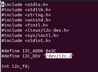
Remember to set I2C_DEV and I2C_ADDR correctly, then compile and run
gcc -o ssd1306 main.c
./ssd1306
The result on the screen will be
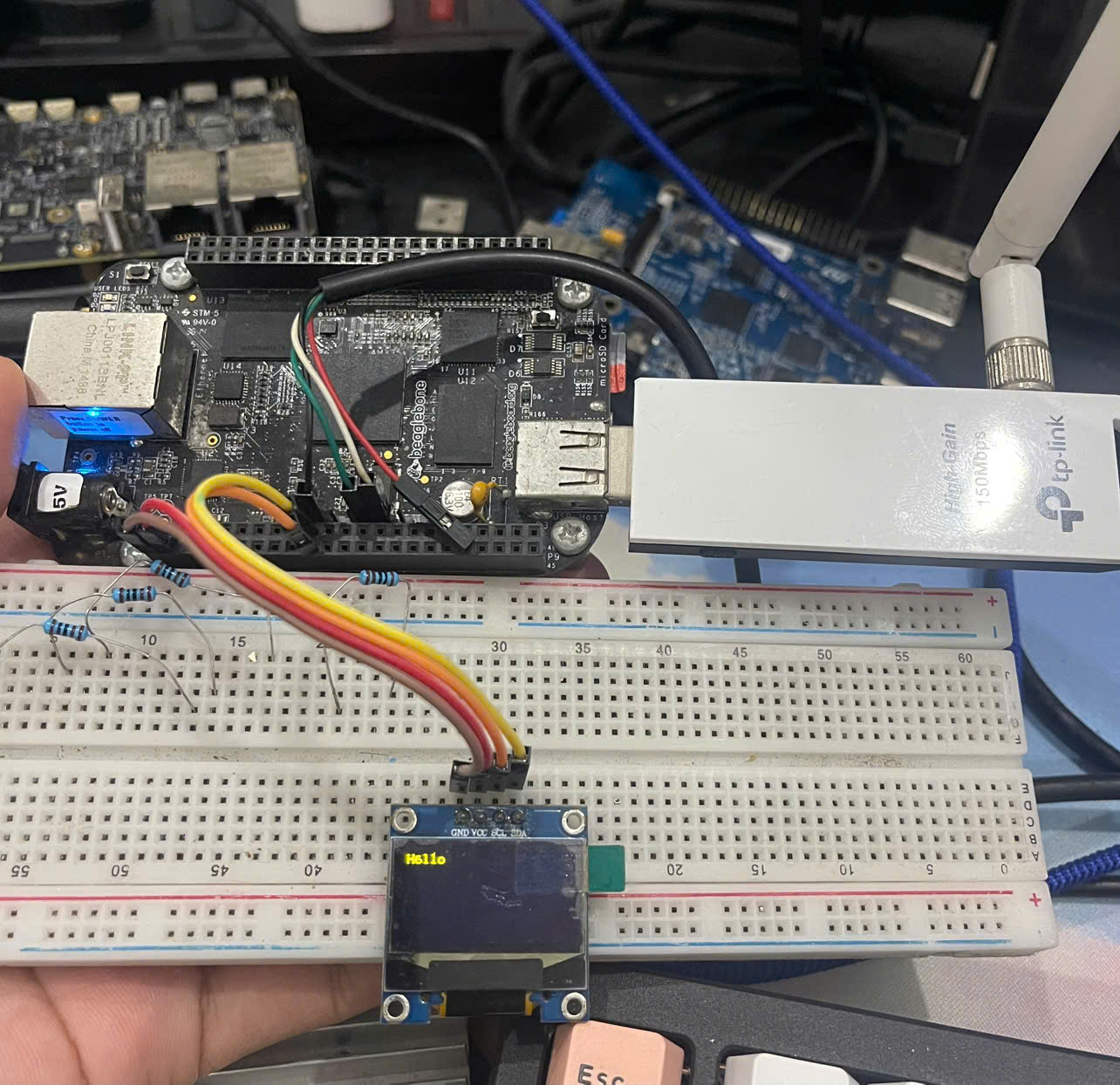
Good luck, and I look forward to contributions improving main.c to support the font properly.
The post is already a bit long, so I will stop here
Look out for the next post, where I will create a recipe that fetches main.c from git and builds it, and show you how to create a patch when the source code is not local.