[Device-Driver-Lichee] 2. Blink an LED with gpioset, create an LED node in the Device Tree
Translated from the Vietnamese original; wording may still be rough. Read the original →
Okay, after part 1 we have a board that boots to a terminal to tinker with; now for the Hello world of the embedded world. Let's try blinking an LED
1. LicheePi Nano pinout
Search online for sipeed licheepi nano and you will find plenty; this is the pinout from Sipeed
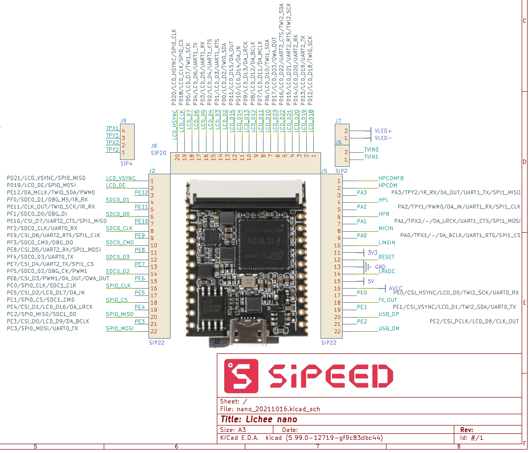
I soldered the pin headers facing down, so the SD card side is on top :vv
For now, basically, connect the UART debug to this board and plug in an LED. I connect the LED through a resistor, cathode to GND, anode to GPIO A3, as in the picture below
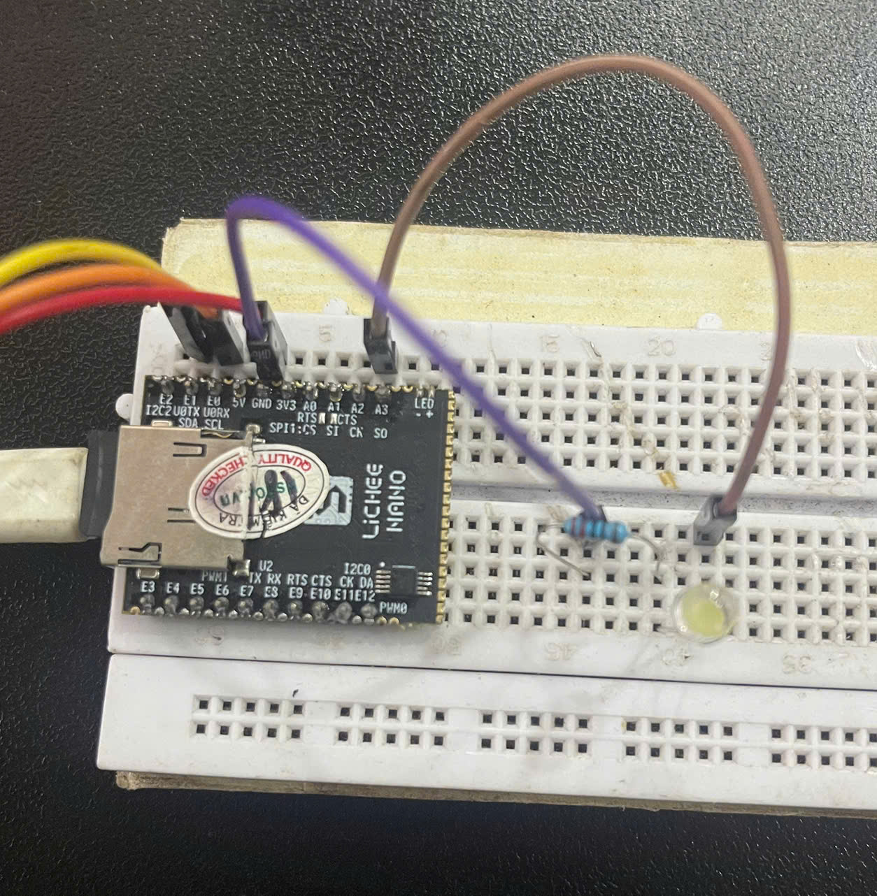
Oh, one lesson learned the hard way: when working with hardware, test the hardware thoroughly first. So instead of connecting to A3, I first connected to the 3V3 pin to check the circuit and see the LED light up :vv. So the hardware has no problem :vv.
So to light the LED we need a high logic level on A3, right?
On to part 2.
2. Using gpioset to blink the LED
2.1 How to work out the GPIO pin number
If you look at the GPIO names on different boards, each board may use its own naming scheme. But in the end it maps to one number. From that number we can work out the address of the register we need to access. For example, if GPIO0 has address 1000, then GPIO1 would be 1032, i.e. an offset of 32 x 1.
In the old days pins were just numbered in increasing order. Nowadays they are usually named with letters + numbers so they are easier to picture and group :vv
Each GPIO bank has 32 pins
Each vendor has its own naming scheme
On the LicheePi Nano board each letter represents a bank: A is bank0, B is bank1, C is bank2, ...
For example PA0 = GPIO-0, PE3 = 32x4 + 3 = GPIO 131
The Beaglebone Black, for example, is different again
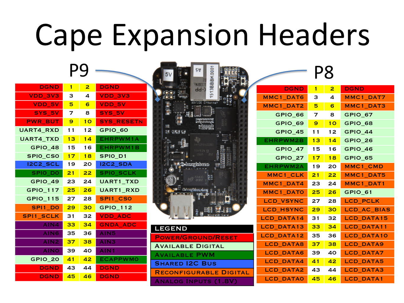
GPIO46   = 32 + 8x1 + 6       = GPIO1 B6

GPIO60   = 32 + 8x3 + 4       = GPIO1 D4

GPIO1 A3 = 1 x 32 + 0 x 8 + 3 = 35

GPIO3 D7 = 3 x 32 + 3 x 8 + 7 = 127
The GPIO1-A3 = GPIO 35 style I came across on the Rockchip RK3576.
In the end, on linux the GPIO + number form is the one used most (for example GPIO 136, GPIO 192)
Okay, so whichever way it is written, we can always convert it to a number
2.2 Using gpioset to blink the LED
Okay, to keep things simple I show you the commands from libgpiod. (Here I use version 1.6)
We need a high logic level to light it, right? So we type
gpioset gpiochip0 3=1
gpiochip0 3 is exactly GPIO0-A3 :vv
Now for the blinking
while true; do
    gpioset -m time -s 1 gpiochip0 3=1   # hold HIGH for 1 second
    gpioset -m time -s 1 gpiochip0 3=0   # hold LOW  for 1 second
done
Now if you check with gpioinfo, you will see GPIO A3 is unused. (Here line A3 has become an output because gpioset handles that automatically) Since it is unused, anything can control it.
root@f1c100s:/boot# gpioinfo
gpiochip0 - 192 lines:
	line   0:      unnamed       unused   input  active-high
	line   1:      unnamed       unused   input  active-high
	line   2:      unnamed       unused   input  active-high
	line   3:      unnamed       unused  output  active-high
On a board with a custom PCB, where I have hard-wired GPIO A3 from the chip to the LED, I don't want this pin exposed to anything else, so we have to declare it :vv
3. Declaring an LED node in the device tree
3.1 What is a device tree?
Simply put, the device tree is a file that defines the hardware present on the board. You can read more at [BBB-Linux] 3.1 Why do we need a Device Tree?
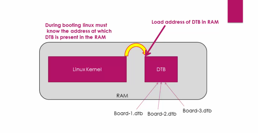
When building a kernel for the same SoC but with different hardware on the board, we used to have to build a completely different kernel image. Now we separate that hardware description into its own loadable file (Device Tree Blob)
3.2 Let's add the LED node
Go to
Lichee-Nano-Device-Driver/linux/arch/arm/boot/dts/suniv-f1c100s-licheepi-nano.dts
Then edit the following (I explain each line in section 3.3)
diff --git a/arch/arm/boot/dts/suniv-f1c100s-licheepi-nano.dts b/arch/arm/boot/dts/suniv-f1c100s-licheepi-nano.dts
index c16838bfe113..d27d7fdcf37b 100644
--- a/arch/arm/boot/dts/suniv-f1c100s-licheepi-nano.dts
+++ b/arch/arm/boot/dts/suniv-f1c100s-licheepi-nano.dts
@@ -27,6 +27,15 @@
                regulator-min-microvolt = ;
                regulator-max-microvolt = ;
        };
+
+       leds {
+               compatible = "gpio-leds";
+
+               led0 {
+                       label = "myled";
+                       gpios = ; /* PA3 */
+               };
+       };
 };

 &pio {
And we rebuild the DTB following the guide from part 1; first we set the toolchain
export ARCH=arm
export CROSS_COMPILE=arm-linux-gnueabi-
Then we build
cd Lichee-Nano-Device-Driver
make -C linux -j$(nproc) suniv-f1c100s-licheepi-nano.dtb
cp u-boot-f1c100s/u-boot-sunxi-with-spl.bin output/
Without those 2 export lines it would call make for the host rather than arm-linux-gnueabi, so we could not cross compile
Okay, now the new device tree is in output/
Plug in the SD card and replace the existing file for the board. (Remember to replace sda with your actual SD card)
 export PART=/dev/sda
sudo umount ${PART}1 2>/dev/null

sudo mount ${PART}1 /mnt
sudo cp output/suniv-f1c100s-licheepi-nano.dtb       /mnt/
sudo umount /mnt
Now checking gpioinfo we see
root@f1c100s:~# gpioinfo
gpiochip0 - 192 lines:
	line   0:      unnamed       unused   input  active-high
	line   1:      unnamed       unused   input  active-high
	line   2:      unnamed       unused   input  active-high
	line   3:      unnamed      "myled"  output  active-high [used]
Now if we deliberately try gpioset it shows an error
root@f1c100s:~# gpioset gpiochip0 3=1
gpioset: error setting the GPIO line values: Device or resource busy
And our LED is located at
root@f1c100s:/sys/class/leds# ls
myled
root@f1c100s:/sys/class/leds# ls myled
brightness      device          max_brightness  subsystem       trigger         uevent
To light the LED we echo 1 to brightness, so to blink it we use
while true; do
    echo 1 >   /sys/class/leds/myled/brightness
    sleep 1
    echo 0 >   /sys/class/leds/myled/brightness
    sleep 1
done
3.3 Explaining the Device Tree node
Looking at the code, after applying that patch we have the following
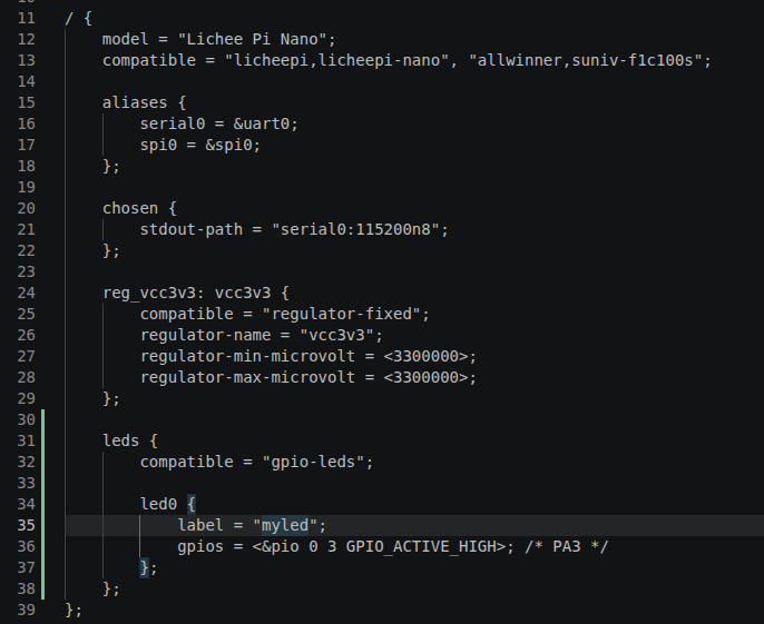
Here
- compatible is which driver you will use. You can see I did nothing to say "store this LED under /sys/class/leds/" or "create brightness". I simply added compatible = "gpio-leds". A driver does the rest. (When you get to kernel modules, this binding will be easier to picture)
- Why define leds first, then led0?
- Because I use the gpio-leds driver, and it requires that. The device tree has a schema to check that the structure and types are correct; if not, the build fails
- label is simply the name of whatever claims this pin, exactly what you see in gpioinfo
- gpios
- to know what &pio is, you need to look at 2 include files
- suniv-f1c100s.dtsi
- dt-bindings/gpio/gpio.h
- Basically, if you have ever programmed registers, there is a define for the GPIO base address, and we use that number to calculate the offset.
- to know what &pio is, you need to look at 2 include files
Oh, you can also install dtc (the device tree compiler) to decompile the suniv-f1c100s-licheepi-nano.dtb file itself, to make it easier to picture
dtc -I dtb -O dts -o decompile.dts suniv-f1c100s-licheepi-nano.dtb
Scroll to the end of decompile.dts and we see
leds {
		compatible = "gpio-leds";

		led0 {
			label = "myled";
			gpios = ;
		};
	};
The &pio defines have been turned into the standard GPIO pin definitions :vv
After the Device Tree Compiler the output is in a common form, whereas if you only look at the dts in the kernel, each board really looks different depending on its macro defines :vv
So depending on the board's defines, we use it slightly differently :vv
Thanks for reading this far !!
Good luck with the hands-on, and look out for the next Device Driver post: gpioget, buttons and interrupts !!