[Device-Driver-Lichee] 3. Gpioget, controlling an LED with a button
Translated from the Vietnamese original; wording may still be rough. Read the original →
I said we would use a button, but I turned my pile of electronics upside down and found no through-hole buttons, only SMD ones. So in this post I use a potentiometer playing the role of a button :vv
1. Connecting the LED and the potentiometer
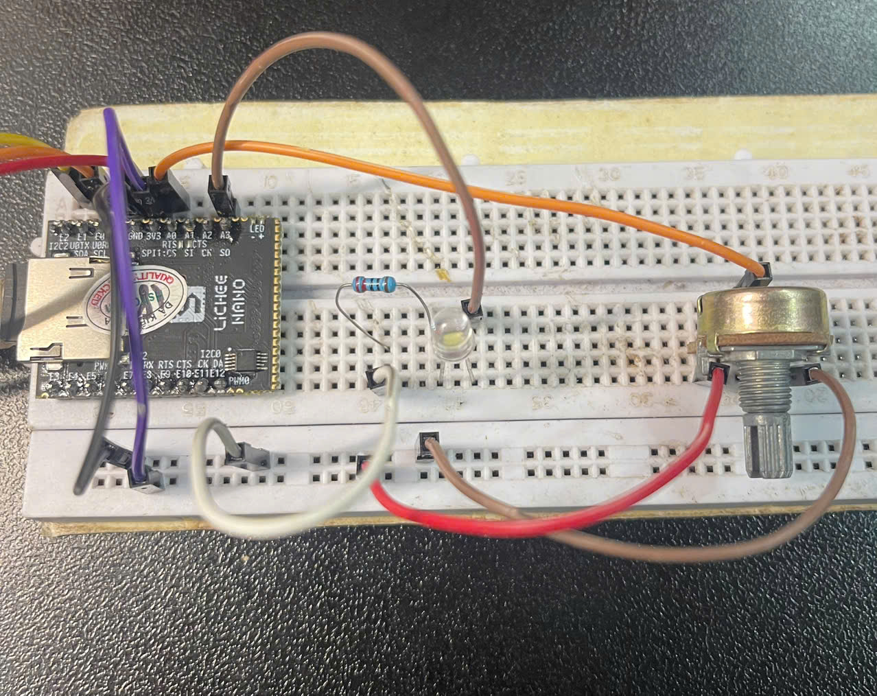
The 2 outer pins of the potentiometer are power and ground; the red wire is 3.3V power, the brown wire is ground
The signal wire in the middle I connect to A0
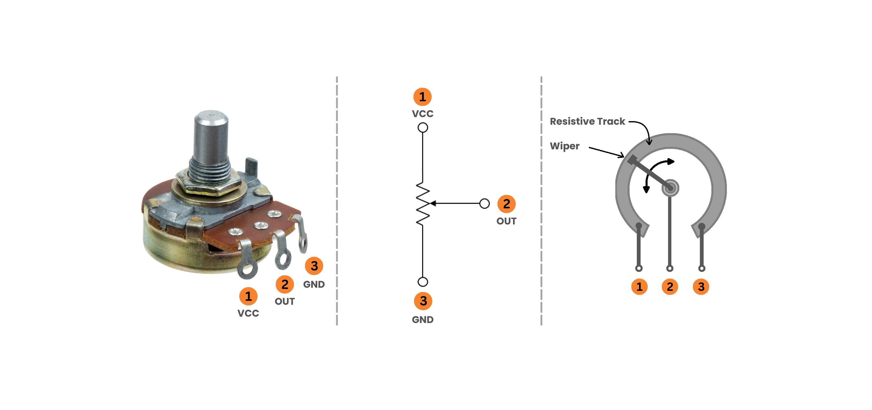
Simply put, if you turn it all the way to side 1, VCC, terminal 2 gets a high level; turn it all the way to side 3, GND, and it gets a low level
2. Checking the logic level
Still with the libgpiod command set, in this post I use gpioget
To watch it visually I combine it with the watch command. Type
watch -n 0.1 gpioget gpiochip0 0
This command checks the gpioget result every 0.1s
3. Using the potentiometer to control the LED
Or, really, using the signal on pin A0 to control pin A3, something like that
3.1 Polling
Polling simply means you keep querying the value from the potentiometer at regular intervals
We run the following simple script, combining gpioget and echo brightness from part 1 (since I defined the LED in the device tree, gpioset can no longer be used)
prev=-1
while true; do
    val=$(gpioget gpiochip0 0)
    if [ "$val" != "$prev" ]; then
        echo $val > /sys/class/leds/myled/brightness
        prev=$val
    fi
done
Here I run a loop that reads the value of GPIO A0 into val; if val differs from the old value, it updates the state and sends it to the LED.
3.2 Interrupts
But instead of the CPU having to poll continuously like that, we should use interrupts. Only when the potentiometer changes to a different logic level do we change the LED state
Here I edit the device tree to define a button. While editing I noticed pin PA0 has no interrupt line, so I switch to pin E3
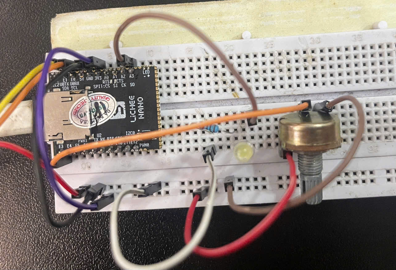
If you insist on keeping pin A0 you get an error
root@f1c100s:~# dmesg | grep button
[    1.562036] gpio-keys buttons: Unable to get irq number for GPIO 0, error -22
[    1.569381] gpio-keys: probe of buttons failed with error -22
After switching pins, we edit the device tree again and rebuild
I add the button node right above the led node from last time
buttons {
		compatible = "gpio-keys";

		button0 {
			label = "button0";
			gpios = ; /* PE3, active low = pressed */
			linux,code = ; /* input event code sent to userspace */
		};
	};
As I described, E3 = GPIO4-3.
compatible: here I use a driver that already exists in linux. In the post after next, on kernel modules, I will describe this in more detail
linux,code = <BTN_0> means I also use linux's own interrupt event; in a moment I will use evtest to show you.
The git diff of the dts file looks like this
                regulator-max-microvolt = ;
        };
+
+       /*
+        * compatible = "gpio-keys": fixed driver name in the kernel,
+        * used for any GPIO button/switch even if it is not a keyboard.
+        */
+       buttons {
+               compatible = "gpio-keys";
+
+               button0 {
+                       label = "button0";
+                       gpios = ; /* PE3, active low = pressed */
+                       linux,code = ; /* input event code sent to userspace */
+               };
+       };
+
+       leds {
+               compatible = "gpio-leds";
+
+               led0 {
+                       label = "myled";
+                       gpios = ; /* PA3 */
+               };
+       };
I made a build script, so now you only need to run
cd Lichee-Nano-Device-Driver
$Lichee-Nano-Device-Driver$ ./scripts/build-dtb.sh
And that's it; then replace the dtb on your SD card with output/suniv-f1c100s-licheepi-nano.dtb and reboot
After rebooting, try these commands
Mine gives the following result
root@f1c100s:~# dmesg | grep button
[    1.566153] input: buttons as /devices/platform/buttons/input/input0
root@f1c100s:~# gpioinfo | grep button
	line 131:      unnamed    "button0"   input   active-low [used]
That means the configuration succeeded; now to test the gpio-keys event we use evtest; the button is registered at input/input0
root@f1c100s:/sys/class/leds/myled# evtest /dev/input/event0
Input driver version is 1.0.1
Input device ID: bus 0x19 vendor 0x1 product 0x1 version 0x100
Input device name: "buttons"
Supported events:
  Event type 0 (EV_SYN)
  Event type 1 (EV_KEY)
    Event code 256 (BTN_0)
Properties:
Testing ... (interrupt to exit)
Event: time 1520602447.153664, type 1 (EV_KEY), code 256 (BTN_0), value 0
Event: time 1520602447.153664, -------------- SYN_REPORT ------------
Event: time 1520602447.903631, type 1 (EV_KEY), code 256 (BTN_0), value 1
Event: time 1520602447.903631, -------------- SYN_REPORT ------------
Event: time 1520602448.603643, type 1 (EV_KEY), code 256 (BTN_0), value 0
Event: time 1520602448.603643, -------------- SYN_REPORT ------------
Event: time 1520602449.013625, type 1 (EV_KEY), code 256 (BTN_0), value 1
To understand evtest better you can read more at [Linux] Configuring a Logitech mouse with Bash scripts
So here we detect the potentiometer state every time the logic level changes, not by polling but through events; every time there is an event we catch it
Combined with controlling the LED with echo brightness, we get the following simple script
evtest /dev/input/event0 | while read line; do
    if echo "$line" | grep -q "BTN_0.*value 0"; then
        echo 1 > /sys/class/leds/myled/brightness
    elif echo "$line" | grep -q "BTN_0.*value 1"; then
        echo 0 > /sys/class/leds/myled/brightness
    fi
done
This approach is still not the proper way, because interrupts should be handled in kernel space; that is why we will have a Kernel module.
Look out for the next post, where I will write about kernel modules !!
Good luck with the hands-on !!